Revision Log for Introduction to Tribology for
Engineers
Ashlie Martini
February 4, 2024
The first version of the textbook (1.0) was published on August 6, 2022. The most
recent version is 1.7 and was published on February 4, 2024. Since the initial version,
multiple edits have been made to improve clarity as well as correct errors. This
document first summarizes the major revisions to content, especially technical errors,
organized by the version in which the change was made. Then, at the end, all
minor edits made between the first and most recent version are compiled by
chapter.
Technical Corrections
Version 1.7 (February 2024)
Section 3.4 Other Surface Characteristics
The description of the correlation length \(\beta ^*\) was revised to replace the phrase about
surface randomness with the statement: “The magnitude of this parameter can
be used to differentiate between surfaces with different lateral spacing of
asperities.”
Version 1.6 (July 2023)
Section 3.3 Roughness Quantification
The use of parentheses in Eqs. 3.9 and 3.10 was misleading as it suggested the
summation should be taken before the third or fourth power. This was corrected by
removing the parenthesis around \(z_i\). The updated forms of Eqs. 3.9 and 3.10
are:
The terminology and variable for conformal contact pressure changed from pressure \(p\)
to applied pressure \(p_a\) in the text and Eq. 4.2.
Section 9.3 Numerical Solutions
Viscous friction force \(F_v\) defined and the reference to Eq. 8.3 modified to correctly
identify it as being used to calculate friction force as opposed to friction
coefficient.
Version 1.5 (April 2023)
Section 9.4 Empirical Equations
The equation for normalized minimum film thickness was missing the effective radius
in the denominator. The corrected Eq. 9.5 is: \[h^{'}_0=\frac {h_0}{R^{'}} \left ( \frac {W}{R^{'} U \eta _0} \right )^2\]
Also, a line was added to clarify that Eq. 9.7 cannot be used for line contact: “Note
that this equation cannot be used as an estimate for line contact since film thickness
is directly proportional to \(k\).”
Section 9.6 End of Chapter Evaluation
Two of the exercise problems were updated (along with their solutions in the
Appendix). The following are the latest version of problems (solutions):
2. The contact between the teeth of mating gears can be approximated as contact
between two cylinders of radius 10 cm. The transmitted load is 100 N and the
relative speed at the tooth contact is 0.5 m/s. The gears are made of 52100
steel and they are lubricated by an oil with 30 mPa\(\cdot \)s and pressure-viscosity
coefficient of 8 GPa\(^{-1}\). Calculate the minimum film thickness using empirical
equations assuming the interface experiences piezoviscous-elastic lubrication. (\(h_{0,PE}=0.19\)
µm)
3. A rolling element bearing has 2 cm radius spherical elements and a 20 cm
radius ring (assume a circular contact patch), all made of 52100 steel. The bearing is
subject to a radial load of 3 N and the relative speed at the ball-ring contact is 5
m/s. For an oil with a viscosity of 40 mPa\(\cdot \)s and pressure-viscosity coefficient of 10
GPa\(^{-1}\), determine the lubrication regime and then use the appropriate empirical
equation to calculate minimum film thickness. (\(h_{0,IR}=0.73\) µm)
Section 10.4 End of Chapter Evaluation
Problem 2 (and its solution in the Appendix) was updated. The following is the
latest version of problem (solution):
2. A human knee joint comprises soft, elastic articular cartilage (\(E^{'}\)=25 MPa)
lubricated by synovial fluid for which viscosity (\(\eta _0\)=2 mPa\(\cdot \)s) does not increase
appreciably with pressure. The knee joint can be approximated as a sphere of radius
4 cm moving with linear speed of 0.2 m/s relative to a spherical cup (socket)
of radius 4.1 cm. Calculate the minimum film thickness at this joint for
person who weighs 200 lbs (assume all of the weight is on the joint). (\(h_0=\) 1.88
µm)
Version 1.4 (November 2022)
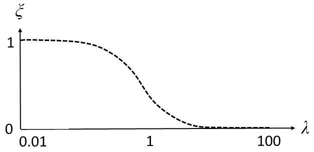
10.5 Friction in Mixed and Boundary Lubrication
The limiting cases of the load support ratio were incorrect. This was corrected in the
following text and updated Fig. 10.5:
“When \(\lambda \) is small, at the transition between boundary and mixed lubrication,
boundary friction is dominant and \(\xi =1\). When \(\lambda \) is large, at the onset of full film
lubrication, viscous friction is dominant and \(\xi =0\).”
Version 1.3 (October 2022)
Section 3.3 Roughness Quantification
The use of parentheses in Eq. 3.5 was misleading as it suggested the summation
should be taken before the square. This was corrected by removing the parenthesis
around \(z_i\). The updated version of Eq. 3.5 is: \[R_q=\sqrt {\frac {1}{N}\sum _{i=1}^{N}z_i^2}\]
Section 4.5 Plasticity
The use of average as opposed to maximum pressure to estimate the onset of
plasticity was corrected. In addition, the discussion of two different models for
maximum shear stress at yield was found to be confusing and unnecessary, so it was
removed. The latest text in this section is:
“The onset of plastic deformation is expected when \(p_{ave} \approx 1.1 Y\), and starts below the surface
at the position of the maximum shear stress \(z_{max}\). Under these conditions, deformation is
partially elastic and partially plastic, also called elastic-plastic. As load increases,
more of the shear stress within the material exceeds the yield criterion and more of
the deformation is plastic instead of elastic. ... The onset of this fully plastic regime
has been estimated to occur at \(p_{ave} \approx 2.8 Y\).”
Section 6.3 Base Oils
The description of the distillation process was revised to improve clarity. The new
text is:
“First, the crude oil is separated into many different “fractions” through a process
called fractional distillation, which takes advantage of the different boiling points of
the hydrocarbons in the crude. The process involves adding heat to vaporize
the crude oil, which then rises up through a vertical column. As the vapor
moves upward, it is gradually cooled. A series of trays collect the material
that condenses (becomes a liquid) at each temperature, as illustrated in
Fig. 6.2. Substances with higher boiling points condense near the bottom
of the column and those with lower boiling points condense closer to the
top.”
Section 9.4 Empirical Equations
A caveat was added to clarify that the minimum film thickness equations were
developed for point contact but could be used to approximate line content. The
following is the new content:
“These equations were developed from numerical solutions for elliptical contacts
with \(k\) between 1 (circular contact) and 36 (elliptical contact approaching the
rectangular shape of line contact).”
Version 1.2 (August 2022)
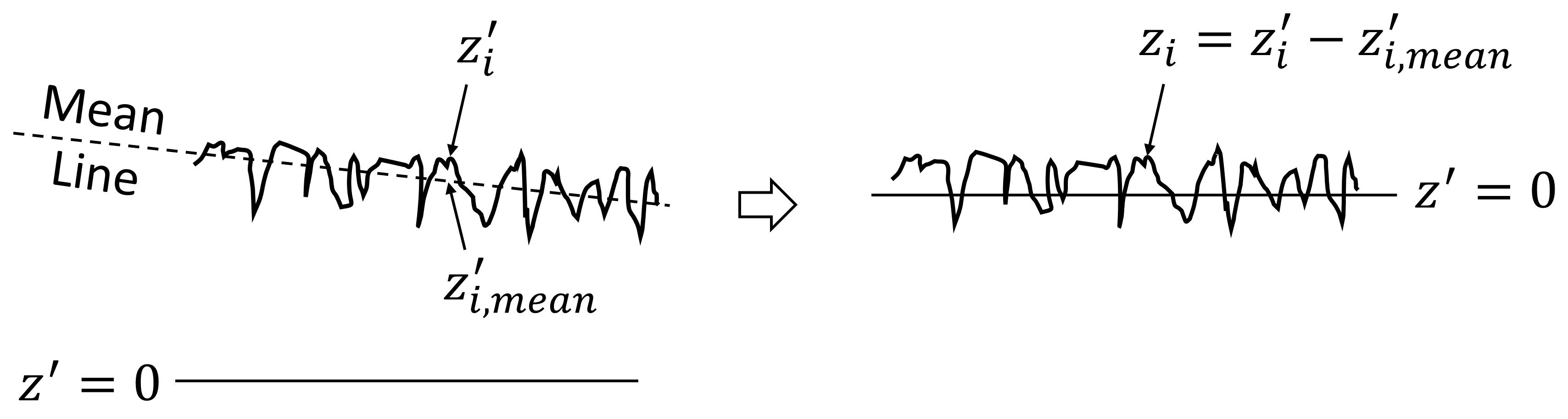
Section 3.3 Roughness Quantification
The variable for reference height was originally given as \(z_{i,mean}\). Since the reference
height is calculated based on raw height data, the variable used should be \(z^{'}_{i,mean}\).
This was corrected in the text and Fig. 3.6. The updated version of Fig. 3.6
is:
Version 1.1 (August 2022)
Section 7.4 Grease Classification
This section originally did not contain information about the grease dropping point,
which is an important metric for grease characterization. The following content was
added to resolve this.
“Lastly, greases are characterized by their dropping point. The dropping point is
the temperature at which a grease changes from semi-solid to liquid. This
temperature is measured by heating the grease in a standard test cup and recording
the temperature at which the grease falls or drips through a small hole at the bottom
of the cup. A grease should have a dropping point above the highest expected
operating temperature for the target application.”
Section 8.2 Hydrodynamic Theory
The explanation of the calculation of the viscous friction force was improved and
simplified. This involved removing the equation for velocity profile (Eq. 8.3 in the
original version of the book). The updated text is as follows:
“The viscous friction force \(F_{v}'\) per unit width is the integral of the shear stress
within the lubricant. For a Newtonian fluid, the shear stress is viscosity \(\eta \) multiplied
by shear strain rate \(\partial u / \partial z\): \[F_{v}'=\int ^l_0 \left (\eta \frac {\partial u}{\partial z}\right )dx\] where \(l\) is the length of the lubricated contact and \(u\) is the local
velocity of the fluid at vertical position \(z\). The fluid speed \(u\) is a function of the local
film thickness \(h\) and pressure gradient \(dp/dx\).”
Section 8.3 Analytical Solution for Inclined Plane
The partial derivative of velocity in the equation for viscous friction force per width
for an inclined plane was changed from \(\frac {\partial u}{\partial x}\) to \(\frac {\partial u}{\partial z}\). The corrected Eq. 8.8 (Eq. 8.9 in the
original version) is:
solid surfaces move \(\rightarrow \) solid surfaces in direct contact move
Although this textbook is intended for engineers, the \(\rightarrow \) This textbook is
intended for engineers, but
In the description of the Stribeck curve: friction \(\rightarrow \) friction coefficient
Figure 1.1 updated to explicitly identify Total Energy Losses
there is no wear \(\rightarrow \) there is minimal wear
Chapter 2
most common engineering ceramics \(\rightarrow \) most common ceramics in tribological
applications
Although brittle materials have a yield strength, it is difficult to measure
\(\rightarrow \) In the case of brittle materials, the yield strength is difficult to measure
Specific heat quantifies \(\rightarrow \) Specific heat \(C_p\) quantifies
High Density Polyethylene \(\rightarrow \) High-Density Polyethylene
prevent corrosion \(\rightarrow \) protect against corrosion
What is a Vicker’s test used to measure \(\rightarrow \) What property is a Vicker’s test
used to measure
Chapter 3
difference in phase between the light reflected off the mirror and the light
\(\rightarrow \) difference between the phase of the light reflected off the mirror and that
of the light
inteferometers \(\rightarrow \) interferometers
the first step is to identify the reference height \(z_{i,mean}'\) and subtract it from the
measured height \(\rightarrow \) the first step is to identify the reference height \(z_{i,mean}'\) and
subtract it from each measured value \(z_i'\)
In Fig. 3.6: \(z_{i,mean}\)\('\) \(\rightarrow \) \(z_{i,mean}'\)
\(R_q\) is the root-mean-square roughness \(\rightarrow \) \(R_q\) is the root-mean-square roughness
(Eq. 3.5)
different levels of roughness \(\rightarrow \) different average roughness
Problem 1 and Problem 2: Units changed from mm to µm; units of
solutions in the Appendix changed accordingly
Chapter 4
Table 4.1 updated to give names of the four shapes
most tribological analyses assume elastic behavior and use the Hertz
equations. \(\rightarrow \) most tribological analyses assume elastic behavior and use the
Hertz equations. However, Eq. (4.5) can be consider the limiting case for
contact area.
Figure 4.6 updated to replace text axis labels with variables and the
caption updated to include variable names
conditions to do the Hertz contact \(\rightarrow \) conditions do the Hertz contact
Chapter 5
will presented \(\rightarrow \) will be presented
viscosometer \(\rightarrow \) viscometer
for non-conformal lubrication \(\rightarrow \) for lubrication of non-conformal contacts
fluid can adsorb form \(\rightarrow \) fluid can absorb from
Why is high thermal conductivity beneficial for a lubricant? \(\rightarrow \) Why are
thermal conductivity and specific heat important for lubricants?
Chapter 6
fraction tapped from each tray boils at the temperature in that tray \(\rightarrow \)
fraction tapped from each tray condenses at the temperature in that tray
greases further also classified \(\rightarrow \) greases are further classified
Group III oils are subject to more strenuous processing than Group II
and are sometimes considered the lowest grade of synthetic oil because of
the level of processing they undergo. \(\rightarrow \) Group III oils are subject to more
strenuous processing than Group II and Group III is sometimes considered
the lowest grade of synthetic oil because of the level of processing such
products undergo.
Chapter 8
The partial derivatives in Eq. 8.1 were changed to full derivatives.
The fact that Eq. 8.1 is the 1D form of the Reynolds equation was clarified.
in the numerator of the equation \(\rightarrow \) in the denominator of the equation
Taking the partial derivative of Eq. 8.6 and setting it to zero \(\rightarrow \) Taking the
partial derivative with respect to shoulder height of Eq. 8.6 and setting it
to zero
solid surfaces are not fully separated \(\rightarrow \) solid surfaces may not be fully
separated
Problem 8.5: 2.5 nm \(\rightarrow \) 2.5 cm
Chapter 9
However, there is also a small “pressure spike” at the outlet of the contact
(near \(x/a\)=1). This position corresponds to a local drop in film thickness as
well. \(\rightarrow \) However, there is also a narrow “pressure spike” at the outlet of
the contact (near \(x/a\)=1). The magnitude of the pressure at the outlet of the
contact can be larger than that in the middle of the contact. The position
of the pressure spike corresponds to a local drop in film thickness as well.
A ratio of the radii of the contacting bodies \(\rightarrow \) The ratio of the radii of the
two contacting bodies
use the entire load on the bearing for a single rolling element \(\rightarrow \) use the load
on the bearing as \(W\) in contact calculations for a single rolling element
In multiple Concept Questions and Exercises Problems: lubrication
category \(\rightarrow \) lubrication type
Chapter 10
few few sliding cycles \(\rightarrow \) first few sliding cycles
Deleted text to avoid confusion: Even without lubricant additives,
boundary friction is lower than dry contact friction because high local
pressures within the contact increase the viscosity of the lubricant. The
resulting very thin, but highly viscous layers can provide some degree of
friction reduction, particularly for boundary lubrication at light loads.
Some materials have even exhibit \(\rightarrow \) Some materials even exhibit
ratio or friction-to-normal force \(\rightarrow \) ratio of contact friction force to normal
force
\(r\) is the average radius of asperities \(\rightarrow \) \(r\) is the average radius of curvature of
the asperities
small amount of the softer polymer will transfer to the surface of the
harder material, called a transfer film, as illustrated in Fig. 10.4. \(\rightarrow \) small
amount of the softer polymer will transfer to the surface of the harder
material, as illustrated in Fig. 10.4. The transferred material is called a
transfer film.
components always operate some of the time \(\rightarrow \) components necessarily
operate some of the time
\(f_m\) is the sum of the contributions \(\rightarrow \) \(f_m\) is due to the contributions
boundary friction coefficient is estimated \(\rightarrow \) boundary friction coefficient is
estimated (Section 10.3)
Rolling adhesion is much smaller than that during sliding \(\rightarrow \) Rolling adhesion
is much smaller than sliding adhesion
friction decrease with lambda ratio \(\rightarrow \) friction decrease with increasing
lambda ratio
Chapter 11
wear coefficient \(K\) that is present in these equations \(\rightarrow \) wear coefficient \(K\) in
these equations
environment will bond with the metal \(\rightarrow \) environment will react with the
metal
vary widely and it is a function of \(\rightarrow \) vary widely since it is a function of
Higher reliability corresponds \(\rightarrow \) A higher reliability goal corresponds
Bubbles form dissolved gas \(\rightarrow \) Bubbles from dissolved gas
adhesion is not a primary wear mechanisms for \(\rightarrow \) adhesion is not a primary
wear mechanism for
However, in contrast to metals, the formation an oxide \(\rightarrow \) The formation of
an oxide
ultra high molecular weight \(\rightarrow \) ultra-high molecular weight
Chapter 12
most benchtop test use \(\rightarrow \) most benchtop tests use
from other tribometer geometries \(\rightarrow \) from any tribometer
benchtop tests to measure wear and characterize wear mechanisms \(\rightarrow \)
benchtop tests and post-test surface characterization to measure wear and
investigate wear mechanisms
Measure the lateral force (friction) \(\rightarrow \) Measure the lateral force (friction
force)
Remove duplicate phrase: also called the breakaway friction
ball creates a circular path ball \(\rightarrow \) travels along a circular path
Wear track from a linear reciprocating ball-on-flat test measured using
an interferometer \(\rightarrow \) Wear track on a flat measured using an interferometer
after a linear reciprocating ball-on-flat test
Problem 1 wear track area changed from 200 µm\(^2\) to 3500 µm\(^2\)
Chapter 13
specialized lubricants were developed that are very thin \(\rightarrow \) specialized
lubricants were developed to be very thin
minimize the head-disk spacing, but still remain on the disk despite the
fast speeds \(\rightarrow \) minimize the head-disk spacing while remaining on the disk
at very fast speeds
leads to graduate material loss \(\rightarrow \) leads to gradual material loss
This means that the same instrument can be used to first wear the sample
and then measure the nanoscale volume of material removed. \(\rightarrow \) sample wear
can be measured using the AFM itself with the load reduced such that
the instrument is a small profilometer.
very high due to layering near the surface \(\rightarrow \) very high near the surfaces due
to layering
synovial fluid to lubricant \(\rightarrow \) synovial fluid to lubricate
New text: Tribological considerations therefore also affect the design of
dental care products.